November 2018 News
November 2018 News

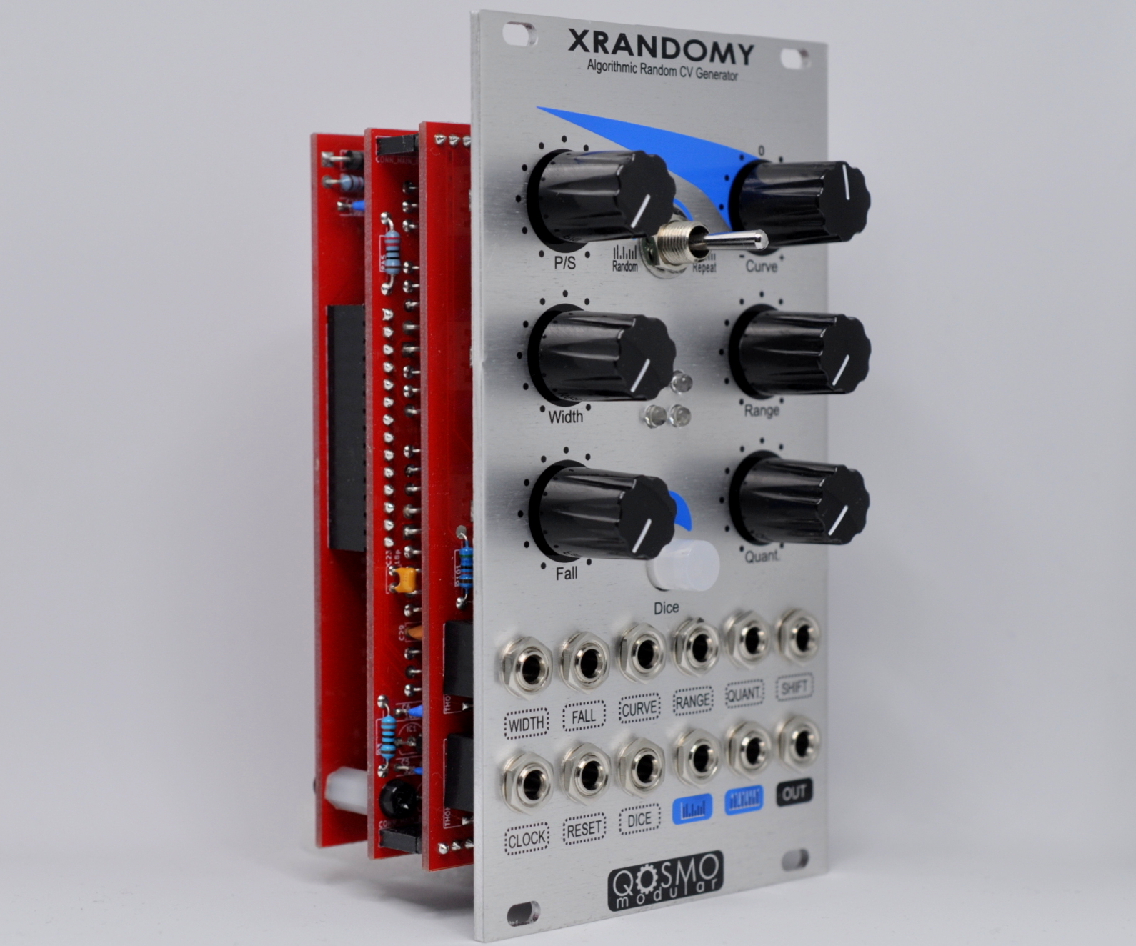
XRandomy
XRandomy is our take on randomness: it’s an algorithmic random voltages generator.
Let’s take a look at the interface panel, we have 6 potentiometers:
-
- Pattern / Step (pot);
- Width (pot);
- Fall (pot);
- Curve (pot);
- Range (pot);
- Quantization (pot);
A switch for the two working mode:
- Random-Random / Random-Repeat (switch);
An illuminated button:
- Dice (button);
For the inputs we have:
- Width CV In, 0-5V;
- Fall CV In, 0-5V;
- Fall CV In, 0-5V;
- Curve CV In, 0-5V;
- Range CV In, 0-5V;
- Quantization CV In, 0-5V;
- Shift CV In, -5V – +5V;
- Clock In, it works between 3-300 BPM but it can also work outside this range;
- Reset In, trigger;
- Dice In, trigger;
e for the outputs:
- Start of Cycle, trigger;
- Start of Step, trigger;
- Main OUT, CV Out, 0-5V;
The module is based on two modes of operation: Random-Random (RR) and Random-Repeat (RP), selectable via the appropriate switch.
At the heart of the module is a White Noise generator appropriately calibrated to generate uniformly distributed random voltages.
Let’s start from RR mode. The module generates at each clock in a random value based on the currently selected algorithm. There are 5 different random generation algorithms, identified by the button blink number:
- No Blink, Algorithm 1, the random value is taken by sampling the internal white noise;
- 1 Blink/s, Algorithm 2, the random value is taken from ROM tables of randomly sampled and sequentially addressed values;
- 2 Blinks/s, Algorithm 3, the random value is taken from ROM tables of randomized sampled values and addressed by the internal White Noise;
- 3 Blinks/s, Algorithm 4, the random value is generated by a Linear Feedback Shift Register whose taps are chosen by the internal White Noise;
- 4 Blinks/s, Algorithm 5, the output is 0 or 5V based on ROM tables of 0 and 1 randomly sampled and addressed by the internal White Noise;
Once the random value of the step has been obtained, the distribution curve is applied, which allows a control on the distribution of the values, favoring the low or high values depending on the position of the Curve pot. In the middle, distribution curve is linear, so the values between 0 and 5V are all uniformly probable. There are 16 distribution curves available.
The range control allows to limit the maximum value that can be generated, expressed in semitones. It is possible to have a range between 1 and 60 semitones (5 octaves).
The Quantization control instead allows to choose the scale according to which the values are quantized, any value outside the allowed is approximated to the nearest allowed level. If the Quantization pot is completely CCW no quantization is applied. 30 quantization scales are possible.
With the Width and Fall controls it is possible to decide how long to hold the value of the step and with the fall it decays towards the 0V value. In particular, Width is the duration of the step expressed as a percentage with respect to the clock in, and the values allowed range between 1% and 100%. Fall, instead, is the speed of falling from the value of the step to 0V. It is expressed with 0-100.
Finally, using Shift it is possible to apply an offset to the value of the step.
In RR mode the reset input has no effect, as it becomes important to trigger the restart from the first step in RP mode, which we will see shortly.
The Dice button, with each pressure, proceeds with an algorithm. In this way it is possible to identify the current algorithm based on the blinks of the button LED. The Dice input is connected to the same control as the Dice button, in practice either by pressing or by trigger / gate the same result is obtained.
The RP mode instead blocks the generation of random values, which are then “freezed”. The module stores up to 32 values and then repeats. With the pot Pattern / Step you can choose how many repeat steps. The allowed values are 1-32 steps.
All other controls work like in RR mode.
Technical specifications:
- All inputs: 100k impedance, DC to 1kHz.
- Width, Fall, Curve, Range, Quantization input range: 0 / +5V.
- Shift input range: -5V / +5V.
- Clock, Reset input range: 1 Khz.
- 10 bit ADC.
- 12 bit DAC.
- Internal processing 32 bit.
- 80 mA +12V.
- 40 mA -12V.
- 0 mA 5V.
- 35 mm deep.
For contacts: info[at]qosmomodular.com
QOSMO MODULAR TEAM